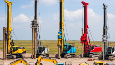
Choosing Well Drilling Equipment begins with a simple question: what ground conditions must the rig handle? A rotary rig can bore through layered rock, while a cable-tool rig works by repeatedly lifting and dropping a heavy bit. Auger systems suit some shallow, unconsolidated formations. The right choice affects drilling speed, borehole stability, water quality, and project cost. Small details matter: a worn bit, mismatched drill rods, or inadequate mud circulation can slow work and complicate well completion.
The scale of groundwater use makes reliable equipment important. The U.S. Geological Survey estimated that the United States withdrew about 82.3 billion gallons of groundwater per day in 2015, its most recent comprehensive national assessment. That figure describes water use—not equipment sales—but it underscores the importance of dependable wells and sound construction. The National Ground Water Association’s technical guidance also emphasizes matching drilling methods to site geology and well design. Field conditions can change quickly. No single rig fits every site.
Hydrogeologist John Cherry, a co-author of the widely used Groundwater Project educational resources, has stressed the need to understand groundwater systems before making decisions that affect them. A practical takeaway for equipment selection is: “Know the formation before choosing the machine.” This is a summary of that principle, not a direct quotation. The guide that follows compares major Well Drilling Equipment types, including rotary, cable-tool, auger, and direct-push systems. It highlights their working methods, strengths, limitations, and typical applications—so readers can assess options with evidence, not guesswork.
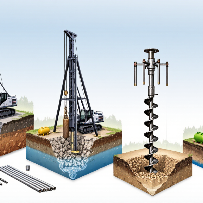
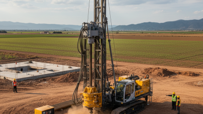
Well drilling equipment is often classified by how it breaks and removes soil or rock. Rotary rigs turn a drill bit while circulating drilling fluid to carry cuttings upward. They are common for deeper wells and varied ground conditions. The setup may use a mud pump, drill pipes, and a fluid tank. In loose formations, casing helps support the borehole.
Percussion systems work differently. A heavy tool repeatedly strikes the ground, breaking hard material into fragments. Cable-tool rigs use this action, while down-the-hole hammer systems combine impact with rotation. Auger equipment turns a helical blade to lift soil, making it useful in softer ground and some shallow wells. No single method suits every site. I still find the categories less tidy in practice, since rigs can combine methods and ground layers can change within a short distance.
Tips: Match the drilling method to a site assessment, planned depth, and expected rock or soil. Check that the equipment can handle casing and remove cuttings effectively. Watch the spoil as drilling progresses; sudden changes in color or texture may signal a new layer. Don’t rely on appearance alone. Keep a drilling log, and confirm decisions with a qualified well professional.
On a rotary rig, drill pipe connects the surface equipment to the bit and carries torque, tension, and drilling fluid. Each joint must withstand changing loads as the string turns and moves through the well. The right pipe depends on the planned depth, hole conditions, rig capacity, and fluid program. A mismatch can increase wear or complicate handling.
API Specification 5DP provides a common technical framework for drill pipe, including material grades, dimensions, and manufacturing requirements. Pipe markings help crews identify key details, such as grade and nominal weight, while records support traceability. Check the connection carefully. Threads and shoulders need to be clean and undamaged before makeup. A small nick can affect sealing or connection life.
Standards matter, but they do not prove that a used joint is fit for service. Inspect for corrosion, dents, worn tool joints, and signs of fatigue; verify wall thickness when required by the inspection plan. Keep inspection records current, and match pipe properties to the loads expected downhole. Paint markings can fade. Even careful checks may miss early damage, so condition assessment needs sound procedures and qualified personnel.
Down-the-hole (DTH) hammers use compressed air to drive a piston that repeatedly strikes the drill bit. The hammer sits close to the bit, so impact energy reaches the rock directly. The action is direct. In hard formations, this arrangement can support steady penetration and help limit energy loss along the drill string. Results still depend on the rock, hole diameter, and equipment setup.
Compressed air powers the hammer and carries cuttings back up the borehole. Airflow must match the hammer and drilling conditions. Too little can slow removal of cuttings and reduce performance. Compressor sizing matters. Operators can track penetration rate, air pressure, and the material returning from the hole. Dusty or mixed cuttings may make changes in the formation harder to interpret, so no single indicator tells the whole story.
DTH systems can be useful for deep holes in competent rock, but they are not ideal for every site. Water-bearing ground, variable formations, and noise or dust constraints may affect the method and setup. A neat-looking collar does not prove that the bore is straight or stable; measurements still matter. That detail is easy to overlook. Regular checks of the bit, hammer, and air supply help identify wear before drilling performance shifts noticeably.
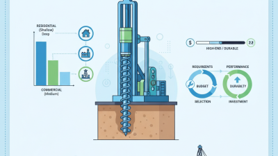
Auger rigs advance a helical steel flight into the ground, carrying cuttings upward as the bit turns. This continuous action can make quick work of relatively uniform soils, such as soft clay or loose silt. The spoil is visible along the flights, which gives the operator a rough sense of changing layers. Rough, not exact. In gravel, cobbles, or unstable saturated sand, the auger may bind or bring up a mixed sample. Water can also make open holes difficult to maintain.
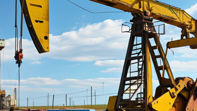
Cable-tool rigs work differently. A heavy bit hangs from a cable and repeatedly drops, breaking the formation by percussion. A bailer then removes the loosened material. Progress is slower, but the method can suit hard or variable formations where a rotating auger struggles. It also allows pauses to inspect cuttings and check water levels. Still, samples can mix between layers, and long pauses do not guarantee a clear picture of the geology.
Choosing between them depends on the ground, the required depth, and what information the well must provide. A tempting mistake is to treat speed as proof of suitability. It isn’t. Site records, nearby well data, and a qualified driller’s assessment help narrow the choice, though subsurface conditions can still surprise a plan. Even a small cobble layer may change the day’s work.
| Comparison Dimension | Auger Rig (Continuous Flight) | Cable-Tool Rig (Percussion) |
|---|---|---|
| Basic drilling action | A rotating helical auger cuts the ground and carries loosened material upward along its flights. | A heavy bit suspended on a cable repeatedly lifts and drops to crush or loosen material at the bottom of the hole. |
| How cuttings are removed | Cuttings travel to the surface on the auger flights and are removed as the auger is withdrawn or cleaned. | Broken material is mixed with water when needed, then removed from the hole with a bailer or sand pump. |
| Ground conditions best suited to | Generally most effective in unconsolidated soils such as clay, silt, and sand, where the hole can remain sufficiently stable during drilling. | Can work in a wide range of formations, including unconsolidated deposits and hard or fractured rock, though progress depends on the formation and equipment. |
| Performance in hard rock | Standard soil augers are not intended for routine drilling through competent rock; specialized tooling may be needed for harder layers. | The repeated impact of the bit can break hard rock, making the method useful where rotary soil drilling is unsuitable. |
| Hole stability and casing | Uncased holes may be vulnerable to collapse in loose or water-bearing ground. Hollow-stem augers can provide temporary support during drilling. | Casing is commonly driven or advanced as drilling proceeds through unstable formations, helping support the borehole. |
| Groundwater considerations | Most suitable where soil conditions allow cuttings to be conveyed effectively. Saturated or loose formations can complicate drilling and borehole stability. | Can be used in water-bearing formations; water may also be added to assist cuttings removal. Water levels and formation conditions affect the drilling process. |
| Typical operating pace | Often efficient in suitable soils because cutting and spoil transport occur continuously during rotation. | Typically slower because drilling relies on repeated impacts and periodic removal of cuttings. |
| Site and setup needs | Requires room for the rig and for handling or disposing of spoil brought to the surface on the auger. | Requires room for the rig, cable system, tools, and handling of bailer returns; repeated impacts can create noticeable noise. |
| Common applications | Soil investigations, shallow borings, and wells in suitable unconsolidated formations, subject to local design and ground conditions. | Water-well drilling in varied formations, including sites where casing support or percussion drilling through hard layers is advantageous. |
| Main advantages | Continuous drilling and spoil removal can make the method productive in appropriate soils; it can also provide relatively direct soil samples. | Versatile across many ground types, capable of penetrating hard rock, and able to advance casing through unstable material. |
| Main limitations | Performance can be limited by hard rock, cobbles, boulders, and unstable or saturated ground; suitability depends on the auger design. | Generally slower and more impact-intensive, with frequent bailing and tool handling required during drilling. |
Selection note: The appropriate rig depends on the local geology, groundwater conditions, required borehole design, site access, and applicable well-construction rules. Actual drilling rates and achievable depths vary with equipment and ground conditions.
Well screens and pumps are closely linked: the screen controls how water enters the well, while the pump must lift that water at a suitable rate. AWWA Standard A100-20 provides guidance for water-well design and construction, with requirements relevant to screens and pumping equipment. Screen openings should retain formation material without restricting flow. Pump selection should reflect the well’s tested yield, water level, required lift, and expected demand.
Small details matter. A screen that looks right on paper may still clog if local sediment conditions are poorly understood.
The USGS report Estimated Use of Water in the United States in 2015 estimated groundwater withdrawals at 82.3 billion gallons per day, about one-quarter of total freshwater withdrawals. That scale makes careful well design more than a technical nicety. For a site-specific decision, review the standard’s current text and use a qualified well professional to assess formation samples and pumping-test results.
Actual conditions can be messy.
Tips
Ask for the screen slot size, pump capacity, and design assumptions in writing. Compare pump capacity with the well’s tested yield, not just the desired flow. Leave room for maintenance; a good design can still need adjustment.