Explore trusted rig components for global markets
Fllow us:

Leave Your Message

Oil Drilling Equipment is the practical foundation of modern well construction. It includes rotary rigs, drill pipes, mud pumps, blowout preventers, casing systems, and directional drilling tools. These machines transfer torque, circulate drilling fluid, control pressure, and protect the wellbore during demanding operations. A single equipment failure can stop work, damage the formation, or create serious safety risks.
Industry demand remains closely linked to energy consumption and field development. The International Energy Agency’s Oil 2024 report projects global oil demand to reach about 105.4 million barrels per day by 2030. OPEC’s World Oil Outlook 2024 presents a higher long-term demand outlook, reaching approximately 112.3 million barrels per day by 2035. Meanwhile, Baker Hughes reported an average global rig count of about 1,771 rigs in 2023. These figures are useful, but definitions and reporting periods differ. The numbers should not be treated as perfectly comparable.
John R. Fanchi, a petroleum engineering scholar and Society of Petroleum Engineers author, describes drilling as “a complex process involving many interrelated disciplines.” That view explains why equipment selection cannot rely on price alone. Engineers must examine formation pressure, well depth, temperature, vibration, maintenance access, and environmental performance. On a rig floor, a mud pump’s steady pulse and the measured torque at the rotary table reveal more than a product brochure. Some planning assumptions will fail. Good operators expect revision, document lessons, and improve decisions through verified field experience. This guide examines what Oil Drilling Equipment is used for, how each system supports safe drilling, and why technical judgment remains essential.
What Is Oil Drilling Equipment Used For?
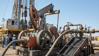
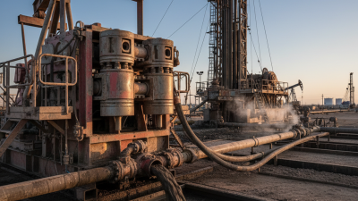
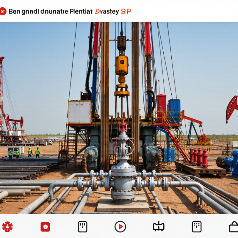
Oil drilling equipment turns a prepared location into a controlled well construction site. The process begins with site preparation, foundation work, and rig assembly. Crews install the mast, drawworks, rotary system, mud pumps, power units, and blowout-prevention equipment. These systems lift tubulars, rotate the drill string, circulate drilling fluid, and control pressure. The International Energy Agency’s Oil 2024 report estimates global oil demand will remain above 100 million barrels per day through 2030, sustaining demand for reliable drilling infrastructure.
During drilling, the equipment creates a wellbore through rock layers with different pressures and strengths. Drill bits cut the formation, while drilling fluid carries rock fragments to the surface. Solids-control units then separate those fragments from reusable fluid. Operators use measurement tools to track inclination, temperature, pressure, and formation response. Casing and cementing equipment reinforce the hole at planned depths. Small errors matter. Poor fluid control can cause stuck pipe or unstable walls.
Well construction is rarely perfectly linear. The International Energy Agency’s Global Methane Tracker 2024 estimates that oil and gas operations released about 120 million tonnes of methane in 2023. This figure highlights the need for better seals, vapor recovery, monitoring, and well-control practices. After drilling, completion equipment installs production tubing, packers, perforating tools, and flow-control devices. The equipment must work as one system, although field conditions often force revisions. That assumption can fail. Experienced crews therefore compare real-time data with the drilling plan before advancing.
| Drilling Stage | Equipment Category | Primary Purpose | How It Works | Typical Data or Operating Range | Contribution to Well Construction |
|---|---|---|---|---|---|
| Site Preparation | Access Roads, Well Pad and Foundations | Prepare a stable and level location for the drilling rig, storage systems and support equipment. | Earthmoving equipment grades the surface, while compacted soil, steel mats or concrete foundations distribute equipment loads. | Pad dimensions and foundation design vary according to rig size, terrain, well depth and local regulations. | Provides a safe load-bearing base and adequate space for rig assembly, fluid handling and emergency access. |
| Rig Setup | Mast or Derrick and Substructure | Support the drilling string, hoisting equipment, work platforms and well-control equipment. | The mast or derrick transfers suspended loads to the substructure and foundation. The substructure creates working clearance above the wellhead. | Land rigs commonly use telescoping or jackknife masts; offshore units use fixed or movable derrick structures. | Creates the vertical working envelope needed to run pipe, casing and completion equipment. |
| Hoisting and Pipe Handling | Drawworks, Crown Block, Traveling Block and Top Drive | Raise, lower and suspend the drill string and casing during drilling and well construction. | The drawworks reels drilling line between the crown block and traveling block. A top drive rotates the drill string from the mast. | Hoisting capacity is selected for the planned hook load, drill-string weight, casing program and safety margin. | Enables connection of pipe stands, tripping operations and controlled placement of tubulars in the wellbore. |
| Rotary Drilling | Drill Bit, Bottom-Hole Assembly and Rotary System | Break and remove subsurface rock to create the wellbore. | The bit applies weight and rotational energy to the formation. Stabilizers, drill collars and downhole tools control trajectory and drilling performance. | Bit types include fixed-cutter and roller-cone designs. Operating parameters include weight on bit, rotary speed, torque and penetration rate. | Establishes the planned well path and produces the open hole required for casing and formation evaluation. |
| Drilling Fluid Circulation | Mud Pumps, Standpipe, Rotary Hose and Flowline | Circulate drilling fluid through the drill string and back to the surface. | Pumps force fluid down the drill pipe; it exits through bit nozzles and returns through the annulus, carrying rock cuttings to the surface. | Flow rate, pressure, density and rheology are adjusted to match formation pressure, hole size and transport requirements. | Cools and lubricates the bit, transports cuttings, supports the borehole wall and helps control formation pressure. |
| Solids Control | Shale Shakers, Desanders, Desilters, Centrifuges and Mud Tanks | Separate drilled cuttings and unwanted solids from reusable drilling fluid. | Vibrating screens remove larger particles, while hydrocyclones and centrifuges separate finer solids according to size and density. | Screen mesh, fluid throughput and separation efficiency depend on the mud system, hole size and drilling rate. | Maintains drilling-fluid properties, reduces equipment wear and supports efficient cuttings disposal or treatment. |
| Well Control | Blowout Preventer Stack, Choke Manifold and Accumulator | Close and control the well if formation fluids enter the wellbore unexpectedly. | Ram and annular preventers seal around pipe or close the wellbore. The choke manifold regulates controlled flow during well-control operations. | Pressure ratings are selected according to anticipated formation pressure, casing design and applicable drilling standards. | Provides a primary barrier against uncontrolled releases of formation fluids and supports pressure management. |
| Power Generation | Engines, Generators, Electrical Distribution and Drives | Supply energy for hoisting, rotation, mud pumping, lighting, instrumentation and auxiliary systems. | Mechanical or gas engines drive generators, which distribute electrical power to motors and control systems. | Power demand depends on well depth, pump pressure, rig design, operating mode and site conditions. | Allows drilling systems to operate continuously and provides controlled power for safety-critical equipment. |
| Wellbore Monitoring | Sensors, Instrumentation and Data Acquisition Systems | Measure drilling parameters and identify changes in well conditions. | Surface and downhole sensors monitor weight, torque, pressure, temperature, flow, vibration, inclination and azimuth. | Real-time measurements support decisions about drilling parameters, trajectory control and well-control response. | Improves operational awareness, helps detect abnormal pressure behavior and supports accurate well placement. |
| Casing Installation | Casing Tongs, Elevators, Slips and Running Tools | Run steel casing into the drilled hole and position it at the planned depth. | Pipe-handling tools lift and suspend casing joints while connections are made and the casing string is lowered into the well. | Casing diameter and grade vary by hole section, anticipated loads, pressure requirements and production objectives. | Strengthens the wellbore, isolates formations and provides a conduit for later drilling and production operations. |
| Cementing | Cementing Unit, Mixing System, Cement Head and Plugs | Place cement in the annular space between casing and the formation or previous casing string. | Mixed cement slurry is pumped down the casing and displaced into the annulus, where it sets and forms a hydraulic seal. | Cement density, slurry volume, thickening time and compressive strength are designed for the well temperature and pressure. | Supports casing, isolates permeable zones and helps prevent unwanted fluid migration between formations. |
| Formation Evaluation | Logging-While-Drilling Tools, Wireline Logging Tools and Mud Logging Units | Evaluate rock properties, fluid content, pressure and the position of geological boundaries. | Downhole instruments or wireline tools record measurements such as resistivity, gamma radiation, density, neutron response and sonic travel time. | Measurements are interpreted with drilling data, core information and pressure tests to characterize the formation. | Helps determine reservoir quality, refine casing points and support decisions about completion and production. |
| Directional Drilling | Steerable Mud Motor, Rotary Steerable System and Measurement Tools | Control the inclination and azimuth of the wellbore. | Downhole tools alter the direction of bit loading or apply continuous steering while measurement systems track the well path. | Trajectory accuracy depends on formation characteristics, tool capability, survey frequency and drilling parameters. | Allows the well to reach a planned subsurface target and can increase reservoir exposure from a single surface location. |
| Well Completion Preparation | Completion Handling Equipment, Tubing Running Tools and Wellhead Systems | Prepare the constructed well for production or injection after drilling and evaluation are complete. | Production tubing, packers, valves and other completion components are installed and connected to the wellhead. | Component selection depends on pressure, temperature, fluid properties, artificial-lift requirements and production strategy. | Transforms the drilled and cased wellbore into a controlled flow path for hydrocarbons, water or injection fluids. |